TOOLS:
- Soldering Iron
- Laptop
- Visual Studio / MATLAB / Any IDE with an Image Processing Library
- AVR programming software / Arduino IDE
MATERIALS:
- 2 Wheels
- 1 Castor Wheel
- Metal Chassis
- 2 DC motors
- 1 Development Board
- 1 Microcontroller (ATmega 16/32/328)
- 1 Programmer (ISP/Arduino)
- Motor Driver (L293D)
- 1 LED
- Relimates
PROBLEM STATEMENT:
Build an image processing robot that can collect resources like food, wood, stone and gold from the arena while avoiding different obstacles using video feed given by an overhead camera.
We’ll split the Problem Statement into Modules.
In this DIY , we’ll step by step discuss each module. The first thing to do is to make a mobile robot capable of moving according to instructions received from the laptop.
PART 1 - A REMOTE CONTROLLED ROBOT:
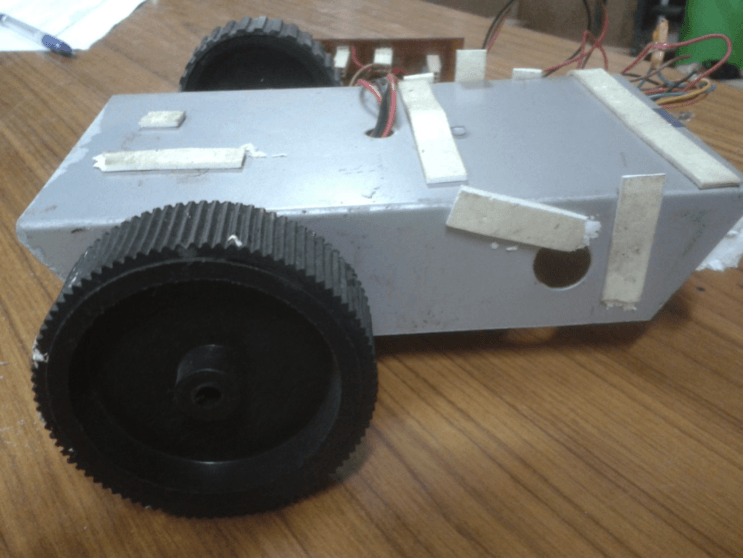
LOCOMOTION
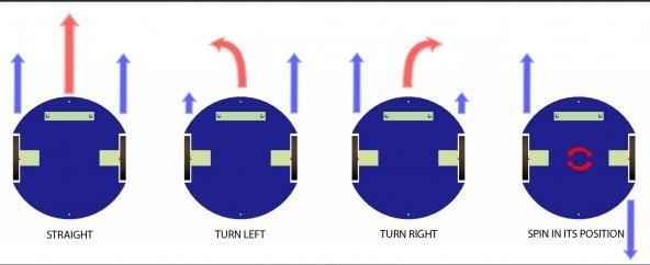
The robot can be made to move by using a differential drive as the base. With independent motors for the left and right sides of the base, differential drives allow the robot to move in all directions and turn as well. How the motors will rotate will be determined by the voltage supplied to the motor by the motor driver circuit, which in turn will depend on the instructions sent to the motor driver by the micro controllers. For more details on differential drives, please check here.
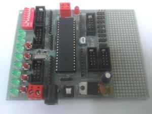
MICROCONTROLLER
Conceived to be the brain of the robot, the micro controller is the device that allows us to control the robot and make it autonomous. By pre-programming it, we can make it give different outputs based on different inputs and instructions received, and thereby the robot acts accordingly. For a more elaborate understanding of the working of an AVR micro controller, please visit here. Essentially you only need to program the micro controller on your robot, to move in a particular direction, based on the character received by it from the laptop.
The code to be burned on arduino is as follows:
#define L_MOTOR_POSITIVE 9
#define L_MOTOR_NEGATIVE 10
#define L_MOTOR_ENABLE 3
#define R_MOTOR_POSITIVE 6
#define R_MOTOR_NEGATIVE 11
#define R_MOTOR_ENABLE 5
#define LED_PIN 13
#define MAX_SPEED_R 240
#define MAX_SPEED_L 180

/*
 * Movements:
 *     W := forward
 *     S := stop
 *     D := right
 *     A := left
 *     R := extreme right
 *     L := extreme left
 *     X := reverse
 */

void setup() {
  pinMode(9, OUTPUT);
  pinMode(10, OUTPUT);
  pinMode(3, OUTPUT);
  pinMode(11, OUTPUT);
  pinMode(6, OUTPUT);
  pinMode(5, OUTPUT);
  pinMode(LED_PIN, OUTPUT);
  Serial.begin(9600);
}

int incomingByte = Serial.read();

void loop() {
  if (Serial.available() > 0) {
    incomingByte = Serial.read();

    Serial.print("I received: ");
    Serial.println(incomingByte);
    if (incomingByte == 'A') {
      digitalWrite(L_MOTOR_POSITIVE, LOW);
      digitalWrite(L_MOTOR_NEGATIVE, LOW);

      digitalWrite(R_MOTOR_POSITIVE, HIGH);
      digitalWrite(R_MOTOR_NEGATIVE, LOW);

      analogWrite(L_MOTOR_ENABLE, MAX_SPEED_L);
      analogWrite(R_MOTOR_ENABLE, MAX_SPEED_R);
    }
    else if (incomingByte == 'D') {
      digitalWrite(L_MOTOR_POSITIVE, HIGH);
      digitalWrite(L_MOTOR_NEGATIVE, LOW);

      digitalWrite(R_MOTOR_POSITIVE, LOW);
      digitalWrite(R_MOTOR_NEGATIVE, LOW);

      analogWrite(L_MOTOR_ENABLE, MAX_SPEED_L);
      analogWrite(R_MOTOR_ENABLE, MAX_SPEED_R);
    }
    else if (incomingByte == 'W') {
      digitalWrite(L_MOTOR_POSITIVE, HIGH);
      digitalWrite(L_MOTOR_NEGATIVE, LOW);

      digitalWrite(R_MOTOR_POSITIVE, HIGH);
      digitalWrite(R_MOTOR_NEGATIVE, LOW);

      analogWrite(L_MOTOR_ENABLE, MAX_SPEED_L);
      analogWrite(R_MOTOR_ENABLE, MAX_SPEED_R);
    }
    else if (incomingByte == 'S') {
      digitalWrite(L_MOTOR_POSITIVE, LOW);
      digitalWrite(L_MOTOR_NEGATIVE, LOW);

      digitalWrite(R_MOTOR_POSITIVE, LOW);
      digitalWrite(R_MOTOR_NEGATIVE, LOW);

      analogWrite(L_MOTOR_ENABLE, MAX_SPEED_L);
      analogWrite(R_MOTOR_ENABLE, MAX_SPEED_R);
    }
    else if (incomingByte == 'R') {
      digitalWrite(R_MOTOR_POSITIVE, LOW);
      digitalWrite(R_MOTOR_NEGATIVE, HIGH);

      digitalWrite(L_MOTOR_POSITIVE, HIGH);
      digitalWrite(L_MOTOR_NEGATIVE, LOW);

      analogWrite(L_MOTOR_ENABLE, MAX_SPEED_L);
      analogWrite(R_MOTOR_ENABLE, MAX_SPEED_R);
    }
    else if (incomingByte == 'L') {
      digitalWrite(R_MOTOR_POSITIVE, HIGH);
      digitalWrite(R_MOTOR_NEGATIVE, LOW);

      digitalWrite(L_MOTOR_POSITIVE, LOW);
      digitalWrite(L_MOTOR_NEGATIVE, HIGH);

      analogWrite(L_MOTOR_ENABLE, MAX_SPEED_L);
      analogWrite(R_MOTOR_ENABLE, MAX_SPEED_R);
    }
    else if (incomingByte == 'X') {
      digitalWrite(R_MOTOR_POSITIVE, LOW);
      digitalWrite(R_MOTOR_NEGATIVE, HIGH);

      digitalWrite(L_MOTOR_POSITIVE, LOW);
      digitalWrite(L_MOTOR_NEGATIVE, HIGH);

      analogWrite(L_MOTOR_ENABLE, MAX_SPEED_L);
      analogWrite(R_MOTOR_ENABLE, MAX_SPEED_R);
    }
    else if (incomingByte == 'V') {
      digitalWrite(R_MOTOR_POSITIVE, LOW);
      digitalWrite(R_MOTOR_NEGATIVE, HIGH);

      digitalWrite(L_MOTOR_POSITIVE, HIGH);
      digitalWrite(L_MOTOR_NEGATIVE, LOW);

      analogWrite(L_MOTOR_ENABLE, MAX_SPEED_L);
      analogWrite(R_MOTOR_ENABLE, MAX_SPEED_R);

      delay(4000);

      digitalWrite(R_MOTOR_POSITIVE, LOW);
      digitalWrite(R_MOTOR_NEGATIVE, LOW);

      digitalWrite(L_MOTOR_POSITIVE, LOW);
      digitalWrite(L_MOTOR_POSITIVE, LOW);

      analogWrite(L_MOTOR_ENABLE, MAX_SPEED_L);
      analogWrite(R_MOTOR_ENABLE, MAX_SPEED_R);
    }
    else if (incomingByte == 'B') {
      digitalWrite(13, HIGH);
      delay(1000);
      digitalWrite(13, LOW);
    }
  }
}
PART 2 – COMPUTER VISION
Before proceeding with this module, we would request you to go through the set of general tutorials for computer vision, for both MATLAB and OpenCV, also found on our website. It is quite extensive, and we will assume that a working knowledge, as put forward there, is in the grasp of the reader of this tutorial.
Note that the video feed will contain some noise. Therefore you will not have a perfect image, and hence detection may become really difficult or you might get wrong predictions. Therefore it is advised to use filters to smoothen your image.
Colour Detection
First thing that needs to be done is that all resources and obstacles need to be identified. We can start with colour detection. Have separate windows for each colour so that only shapes with the required colours are displayed in the respective window.
Detecting Contours
We need to scan the shapes present in the arena using an overhead camera. A good approach to solve this problem would be to segment out the shapes from the image that is taken by the camera. Use bounding rectangles to take out the portion of the image containing the shapes. A method called contour detection can be used to figure out the bounding rectangle.
Shape detection
After colour detection, shapes are to be identified to distinguish between two resources of the same colour or a resource and an obstacle of the same colour.
Optimization and Path
The next step is to deduce the order in which resources will be collected. Different types of resources have different scores. Resources have to be collected in such an order that the total score in a given period of time is maximized.
Next step is to figure out the path from one point to another, rather from the town centre to the resources while simultaneously avoiding any obstacles encountered on the path. There are many path planning algorithms for this. One of which is RRT or Randomly Exploring Random Tree.
RRT : A Rapidly-Exploring Random Tree is a randomized data structure that is designed for path planning problems.
In any image where RRT has to be implemented, there will be a start point, an end point and obstacles. The start point is taken as the first node, and the end point is taken as the last node. The first step is to generate a random node. Using distance formula, the node (in the tree) which has the minimum distance from this random node among all other nodes in the tree is identified. /tarting from the nearest node, in the direction of the random node, a new node is generated at a predefined distance called step size. This new node is then added to the tree. These steps are repeated n number of times till the end point is added to the tree. Then a continuous path is traced from the start point to the end point which successfully avoids all obstacles. This process results into a tree-like structure, hence the name Rapidly-Exploring Random Tree.
However, participants are free to use any path planning algorithm they are comfortable with.
Tracking the Position of the Robot
Throughout your run you will require to track the position of the robot. A marker for the same will be provided. The marker will consist of two squares with different colours. RGB values of the colours will be provided. First we need to scan the input image to get all the points whose colour is roughly the same as the colour of square 1/Head. The centre of all these points is the centre of the Head. Similarly we can find the centre of the Tail. The geometric midpoint of these centre can be fairly estimated as the Position of the Robot.

Locomotion of the Robot
Now that we know the position of the bot and the position of every subsequent shape, we need to send commands to the robot so that it moves to that particular position. Since all the readings are not accurate with the help of overhead camera we just need to move the robot so that its distance with respect to the subsequent position is less than a certain threshold.