Problem Statement:
To build a robot that is capable of making a building by successfully receiving the number of blocks required sent using wireless communication and differentiating between hollow and solid bricks by successful autonomous weight detection.
USP:
-
Weight measurement
-
Buttonless traversal
-
Wireless data communication.
Weight Measurement
1.Force sensitive resistor
A force sensitive resistor or an FSR is a resistor which changes its value when a load is applied to it. This property can be used to measure weight of different objects.
The following circuit can be used to measure weight:
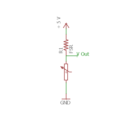
The V-out pin is attached to analog pin of arduino and can be calibrated as required. This sensor detects with from 50 grams to 1 kg. Force Sensitive Resistor can be purchased from this link.
2.Flex sensor
Flex Sensor or Bend Sensor is a sensor that changes its resistance depending on the amount of bend on the sensor.They convert the change in bend into electrical resistance – the more the bend, the more the resistance value.Flex sensors are widely used in various applications such as – Automotive controls, Medical Devices, Fitness Products, Virtual Reality gaming consoles, Animatronics, Robotics, etc.Flex Sensor’ or ‘Bend Sensor’ is a sensor that changes its resistance depending on the amount of bend on the sensor.They convert the change in bend into electrical resistance – the more the bend, the more the resistance value.Flex sensors are widely used in various applications such as – Automotive controls, Medical Devices, Fitness Products, Virtual Reality gaming consoles, Animatronics, Robotics, etc.
How it Works
One side of the sensor is printed with a polymer ink that has conductive particles embedded in it. When the sensor is straight, the particles give the ink a resistance of about 30k Ohms. When the sensor is bent away from the ink, the conductive particles move further apart, increasing this resistance (to about 50k-70K Ohms when the sensor is bent to 90°, as in the diagram below).
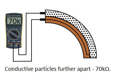
When the sensor straightens out again, the resistance returns to the original value. By measuring the resistance, you can determine how much the sensor is being bent.
The flex sensor is designed to be flexed in just one direction – away from the ink – as demonstrated in the image below.
Bending the sensor in the other direction will not produce any reliable data, and may damage the sensor. Also take care not to bend the sensor close to the base, as they have a tendency to kink and fail.
Example Circuit:
The simplest way to incorporate this sensor into your project is by using it in a voltage divider. This circuit requires one resistor. Many values from 10KΩ to 100KΩ will work. If you have a resistor kit, you may want to introduce some trial-and-error to hone in on that perfect static resistance.
A value between the minimum and maximum resistance values is usually a good choice. We’ll use a 47kΩ resistor in this example.
3.Load sensor
A load cell is a physical element (or transducer if you want to be technical) that can translate pressure (force) into an electrical signal.
Hydraulic Load Cells
Hydraulic load cells use a conventional piston and cylinder arrangement to convey a change in pressure by the movement of the piston and a diaphragm arrangement which produces a change in the pressure on a Bourdon tube connected with the load cells.
Pneumatic Load Cells
Pneumatic load cells use air pressure applied to one end of a diaphragm, and it escapes through the nozzle placed at the bottom of the load cell, which has a pressure gauge inside of the cell.
Load Cell Set Up
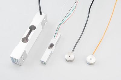
A selection of different load cells
Depending on the type of load cell you are using, the configuration of how it should be hooked up to plates or surfaces will change.
Note that only one side of the load cell is screwed into each board. This provides a moment of force, or torque, on the strain gauge rather than just compression force, which is easier to measure and much more accurate.
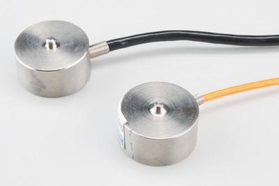
For smaller, push-button or disc load cells, you will want to make sure to screw in the disc to a bottom plate (or surface you are measuring force against), and center the beam, plate, or whatever else you are wishing to measure the force of onto the “button” on the top. Usually another plate with a hole is used to make sure whatever you are measuring is hitting the same spot on the load cell each time, but it is not necessary.
Make sure to read the datasheet for the load cell you are using and get the correct screws to fit into it.
Load cell measurements can be off by +/- 5% due to a range of things including temperature, creep, vibration, drift, and other electrical and mechanical interferences. Before you install your scale, take a moment and design your system to allow for easy calibration or be able to adjust the code parameters to account for these variations.
Wireless Communication:
First we will start with what serial communication is.
The Serial library can be used to communicate between Arduino(s) and computers over a USB cable (wired) or Bluetooth/Zigbee (wireless).This inbuilt library contains built-in functions for the same. In fact, it is used implicitly when we upload sketches/programs to the Arduino.
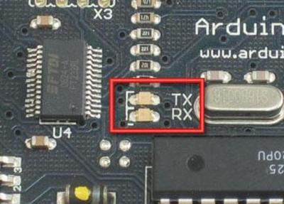
There are two data lines in serial communication, RX and TX, which stands for receiver and transmitter. A communication wire, e.g. USB typically connects the RX pin of the Arduino to the TX pin of the computer; and the TX pin of the Arduino to the RX pin of the computer. The board has a couple of LEDs which light up when data is being received / transmitted.
Basic Communication
If you face issues while uploading the code, make sure that pins 0 and 1 of the Arduino are not connected to anything, since they double up as RX and TX pins.
The Serial.begin() function starts off the communication channel. The 9600 parameter is the data rate in bits per second, which must be the same for both the receiver and the sender.
The Serial.println() function takes in a string or variable and transmits it, followed by a new line.
Upload the sketch on the board, and press Ctrl+Shift+M to bring up the Serial monitor.
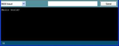
The monitor displays all incoming data from the board, as well as allows sending data to it. The Serial.read() function returns the last received character by the Arduino, and is illustrated in the next example.
Another useful function is Serial.available() which returns true at the moment the Arduino receives data. It can be used effectively inside a loop to check for incoming commands.
Moving on to Wireless
So far, we have controlled our robot through a USB cable. We can extend this into a wireless solution using the following communication methods:
-
Radio Frequency Modules
-
Bluetooth Modules
-
ZigBee / Xbee Module
Having multiple bluetooth modules with the same name can be confusing. Sometimes it may require to change the default settings like baud rate, or master/slave role of the module. This guide shows how to enter AT command mode of HC05/HC-06 bluetooth module with the help of USB to TTL converter. Alternatively for HC-05, you can use an arduino board.
Requirements:
1.HC-05/HC-06 Bluetooth module with breakout board.
2.USB to TTL converter : We’ll use arduino uno in this tutorial, other boards should work to.
3.Arduino IDE/ Tera Term : It can be downloaded from here or if you don’t want to download arduino then download Tera Term from here.
Step 1: Identifying your module

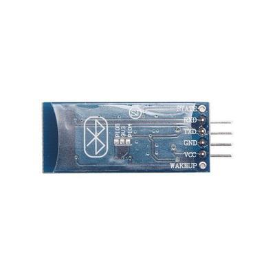
First thing you need to do is identify your module. It can be either HC05 or HC06. Both the modules are same in functionality except the pinout. Also HC05 can act as both master and slave whereas HC06 functions only as slave. It’s hard to differentiate between the two only by seeing. One probable way would be checking the back of the breakout board. If it has “JY-MCU” written on the back, it’s probably a HC06. Mine has “ZS-040” written and it is a HC05. And the HC06 module I tested had a bluetooth sign behind with three pcb footprints(refer to figure2). To confirm the device identity, you can power up the module, search for new device on your pc or mobile, and look for HC05 or HC06 on found device list.

Gesture Control
The gesture controlled robot uses Arduino, ADXL335 accelerometer.
The different gestures that can been mapped to the direction of the bot are-
-
Hand parallel to the ground-stationary
-
Hand tilted forward-forward
-
Hand tilted backward-backward
-
Hand tilted right-right
-
Hand tilted left-left
Step 1: Materials required
For Gesture control
-
Arduino Uno
-
ADXL335 accelerometer
For robot-
-
Arduino Uno
-
L293D motor driver IC
-
Chassis and wheels
-
2 DC motors
Of course you will also need jumper wires and 9V batteries.