Problem Statement:
To build a manually controlled robot which is capable of cutting the required wires and lifting objects.
To tackle this your robot needs a mechanism having a:
-
Cutting Capability
-
Land Traversal capability
-
Robotic arm
-
A storage mechanism (optional)
How this Tutorial works
This is a guide for an enthusiast like you to explore your own imagination and incorporate them in your robot for ROBOTIX’ 17 edition. The tutorial lists out all the skills that the event requires your bot to have and tells you exactly how you can implement each of them. And finally, find our ‘Tips’ to put together all your mechanisms and build a winning robot!
MECHANISMS FOR CUTTING
1.Rotating Saw Mechanism
Design:
The Mechanism consists of a high speed DC motor connected coaxially with a circular blade. The setup works similar to a chain saw and when the motor rotates at high RPM, it cuts through the wire.
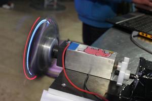
Material Required:
-
DC Motor
-
Circular Blade
-
Wires
Steps for Construction:
-
Mount the DC motor on the robot platform.
-
Connect the Rotating disc to the axle of the motor coaxially.
-
Connect the motor to the power source with wires.
Working:
As the rotating blade comes in contact with wires, it receives an impulse at very small surface area that cuts the wire from that point.
2.Scissor Mechanism
Design:
The mechanism works when a mechanical scissor is connected to robotic gripper. The force applied by the gripper is concentrated on a very small area. The pressure thus created on the wire cuts it from there.
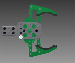
Material Required:
-
Robotic Gripper
-
DC Motor
-
Scissor to connect to the gripper mechanism
-
Wires.
Steps for construction:
-
Attach the robotic gripper with the motor.
-
Attach the scissors at the end of the gripper.
-
Connect the motor of the gripper.
-
Connect the motor to the power source using wires.
Working:
-
The gripper basically consists of a motor and set of gears.
-
When the motor is powered, the motor rotates in one direction which in turn rotates the gear that makes the gripper to close.
-
When the motor rotates in reverse direction, the gripper gets opened.
MECHANISMS FOR TRAVERSALS
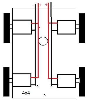
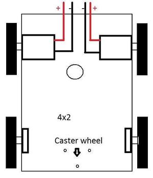
1. Differential Drive Mechanism
Design:
When two motors are connected to wheels in one line, opposite to each other (just like a pair of wheels connected to a single shaft) the speed with which each motor rotates determines the direction of motion. When both the wheels rotate at the same speed the difference between the motors is zero. This makes the robot move forward in a straight line.The robot can move in reverse direction if the direction of rotation of both the motors are reversed. This will again be in a straight line if the speed difference is zero.
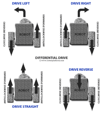
Now changing the speed of any one motor will result in movement in a direction away from the straight line. For example, reducing the speed of the right motor will result in a speed difference and hence change in direction.The resultant force is such that the robot turns right. This direction change can be controlled to required angle by further reducing the speed of the motor.Slower is the right motor, sharper is the turn to right. This is exactly the same for Left turn.
As a conclusion, Slower right motor, sharper right turn. Slower left motor Sharper left turn. Below are some scenarios which explains working of differential drive mechanism.M1 and M2 are motors which drive wheels on left and right respectively.
Material required:
-
Basic rectangular chassis
-
Four DC Motors / Two DC Motors
-
Wires
-
Four Wheels / Two Wheels and One Caster Wheel
Steps of construction:
-
Make the Wheel Template.
-
Cut-out the wheels, and drill a hole in the middle.
-
Join the wheels to the chassis with connecting axles.
-
Join the motors to the wheels.
-
Make connections of your motor to the circuit of Differential drive.
-
Your robot is ready to work.
Working:
-
When both the wheels turn forward with same RPM the robot goes forward
-
When both the wheels turn in reverse direction with same RPM the robot goes backward.
-
When left wheel turns forward and right wheel turns backward the robot takes zero radius right turn. Vice versa happens in the case of left turn.
-
When left wheel turns forward but right wheel turns forward with lesser RPM than left wheel then the robot takes right turn with particular radius of curvature. Vice versa happens in the case of left turn.
Controls:
Three way switch

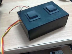
Motor Connections:
The motors are fixed to the chassis and the tyres are fitted to the DC Geared Motors.
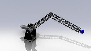
ROBOTIC ARM MECHANISM
1.Mechanical Arm
Design:
In this mechanism we have used a manually controlled robotic arm with 2 degrees of freedom.
Material required :
-
2 DC Motors.
-
Rack and pinion mechanism(for the rails).
-
2 elbow joints in perpendicular planes of the arm.
Steps of construction:
-
Connect one motor to the base of the whole arm mechanism. This will help in turning the arm left and right.
-
Connect the other motor to the arm such that its motion causes the arm to move up and down.
Steps of construction: (Gripping mechanism with motors)
-
As shown in figure, keep one side of the part stationary.
-
Attach motor to the end of another part.
-
Make wire connections of the motor such that when the motor is rotated in one direction one part moves towards other part (stationary) and vice versa.
Working:
A simple mechanical arm consisting of two motors. The first motor controls the upward and downward movement of the arm. While the second one helps helps in rotating the arm sideways.The arm provides 2 degrees of freedom to move in horizontal as well as vertical direction, so that the arm can reach all the ends of the arena.